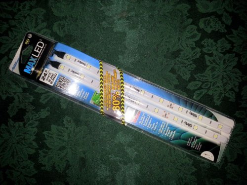
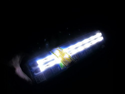
Let's talk LEDs & Load Resistors please

RigsLS

Dedicated LVC Member
Joined
Mar 10, 2012
Messages
7,756
Reaction score
533
Guys, I've searched around and I'm just unsure on this.

I picked up,

>> Two Xenon HID WHITE T10 168 2825 194 W5W 6-LED Lights ~ for my plate lights.
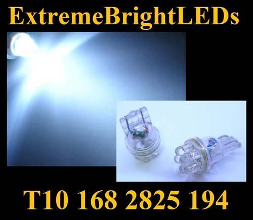
$(KGrHqQOKo0E4t869VCeBOWumi4)8Q~~60_12.JPG


>> Two Xenon HID WHITE 3156 3157 24-LED Backup Lights ~ for my backup lights.

$(KGrHqV,!k8E-bz5lqRzBP4fy042OQ~~60_12.JPG


>> One WHITE 42mm 1.72" 578 211-2 212-2 9-LED Map Dome Door Light Bulb ~ for my trunk.
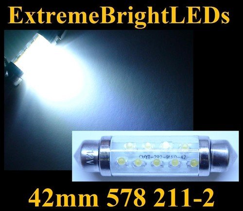
$(KGrHqJ,!i4E8Ueq7iDHBPI2-t0!pQ~~60_12.JPG


Trouble is, there are resistors inside the LED housing, it let me to believe that they were error free, plug n play.

This is not the case, on my 01 gen 1 LS Sport they stay on dimmed and only go out after 30mins or so.

I have no idea of the wattage, it's not written directly on them and I have no clue as to what size resistors I need to add to get them to go out immediately.

Looking back on my eBay purchase I may have settled for "cheaper" versions if you will.


Any tips from anyone that has successfully install LEDs on a 1st gen and managed to get them to stop dimming with a load resistors ?

How does one determine what size resistor and is there more to it ?

Thanks so much in advance.

$(KGrHqQOKo0E4t869VCeBOWumi4)8Q~~60_12.JPG


$(KGrHqV,!k8E-bz5lqRzBP4fy042OQ~~60_12.JPG


$(KGrHqJ,!i4E8Ueq7iDHBPI2-t0!pQ~~60_12.JPG
 
Error free LED bulbs are specifically designed with built-in load resistors to allow them to be used
with CAN(Controller Area Network) Bus equipped vehicles without triggering the OBC (on-board computer),
commonly found in European vehicles such as BMW, Audi, Mercedes, Volkswagen, Porsches.
CAN Bus bulbs should not be used in non CAN Bus applications


CAN Bus bulbs should not be used in non CAN Bus applications

Our LS's have a CAN Bus ??? :confused:
and therefor these types of LEDs should not be used ??? :confused:

The Gen2 uses the CAN/BUS. The 1st gen does not.
 
OK thanks LS4you,

Perhaps I shouldn't be using these LEDs on this Gen1 then, they do work, no warnings on the dash.

Need them to go out immediately with a load resistor I guess.
anyone.gif
but they already have the resistors in them.

I don't get it.
 
on my 01 gen 1 LS Sport they stay on dimmed and only go out after 30mins or so.

That's normal. All my LEDs do it. The LEDs use less power so the stay on like than until the residual power is gone basically. It doesn't do with the regular bulbs since they require more power to turn on.
 
Gen I backup lamps are different from Gen II? I just bought some 921s for mine..
 
Yes they are, I was looking at that as well, you have the right ones and I had to get the 3157 for the Gen I.
 
...How does one determine what size resistor and is there more to it ?

Thanks so much in advance.

You need to know two things to do this.
1. How much current does the LS bulb minder circuit source (I)?
2. What is the minimum voltage needed to light the LEDs (V)?

Subtract one or two volts from the minimum voltage just to be safe.

R (resistance) = (V-2) / I

You also need to know the power rating needed for the resistor.

P (power) = V^2 / R (where V = 14.5 volts this time)
Since this is in a hostile environment, you should probably get one with a power rating of at least twice what you calculated.

Here's an example with numbers, but the current and voltage are wild guesses on my part. You'll need to measure to be sure.

Assume (guess) a sense current of 10 mA (0.01 A) (it's probably less than this)
Assume a min voltage of 6 volts (no bets on this one)

R = 4 / 0.01 = 400 ohms

P = 210.25 / 400 = 0.5256, so double that and you need a 1 watt resistor at 400 ohms.

The reality is that when you measure the actual values you will probably find that you can use a higher value resistor of lower wattage.
 
Thanks Joegr, although it's almost Chinese to me, it's starting to make a bit of sense.
 
Looking to add these to the trunk and wire into the trunk light bulb.

20130304_174433.jpg

20130304_174514.jpg

20130304_174433.jpg


20130304_174514.jpg
 
and it dims or turns off completely ?


the real issue is that the LS uses a negative trigger system, meaning that at the light bulb there is always positive 12v, and the computer switches the ground on and off, when the computer "falls asleep" there is a high resistance to ground, and a very small amount of power will flow through the bulb and the resistance. this same amount power still flow through standard incandescent bulbs, except for there is not enough power to heat up the filament enough to glow. since LED's are so much more efficient, that small amount of power will actually cause the bulb to light a little. placing a high enough resistance resistor in parallel with one of the bulbs gives the power another path to take instead of through the bulb so it wont light up anymore.

from: http://www.lincolnvscadillac.com/showthread.php?t=77457


Soldier one side of the resistor to the + side of the wire and the other side of the resistor to the - of the wire, done.

puddles001.jpg
 
On my Gen1 I used a utility light wired into the stock light. I did have to use a relay to make it work, but that trunk is like daylight at night!
 
I'm looking for information on the size of Resistors I should be using from someone
that has successfully managed to get the LEDs to turn off 100% immediately on a Gen I.
 
I'm looking for information on the size of Resistors I should be using from someone
that has successfully managed to get the LEDs to turn off 100% immediately on a Gen I.

And I'm looking for information on how to earn enough $$$$$$ (legally) to afford a new M5.... ;)
 
Bet the M5's don't have issues with LEDs.
 
For BigRig...

Looks like there are 6 main resistors (color stripes: Red, white, blue, white, black, red....i think) and i smaller resistor (red, white, blue)... these control 18 LEDs.


under the red power wire is the 7th resistor (smaller)...

20130313_192226_zps62d63a84.gif

20130313_192011_zpsdb700822.gif

20130313_191951_zps6450f4d0.gif

20130313_191943_zps0e6e6810.gif

http://i1184.photobucket.com/albums/z336/G-
RELL1/20130311_173852_zps40f32cdf.jpg

HOPE THIS HELPS!
 
Thank G, load resistors, color bands, very interesting.

I ended up picking up some different load resistors yesterday and am going to try
joegr's math on finding what the load on all my LED's in the trunk add up to.

This top mount brake light LED is obviously also load resistor circuit designed to extinguish the LED's.

I so now regret not grabbing the Top Mount light out of the 03 before they scrapped it.

I'll find another one.

oh: if you wire that directly to your GEN I and it works without issue, would you let me know ?

Thanks again G.
 
hard to make out by the pics, looks like the leading band is "gold"

Joegr, you wouldn't by chance happen to have the wiring diagram on these GEN II top mount brake lights ?
( I myself only have the GEN I shop manual with it's wiring diagram and GEN I uses a single bulb instead of LED's.)

Looks like one resistor per two LED's.

Yes, I have the wiring diagrams for gen II, but they just treat the 3rd light as an assembly.
Those aren't "load" resistors. They are current limit resistors for each pair of LEDs. They are needed because the LEDs are not 12V devices.

The gold band is for tolerance. That's not particularly important in this application. The resistors should be three color bands plus the gold band. If they were 1% resistors, it would be four bands. Anyway, the six colors called out are too many.
 
Looked at the picture closer. It's blue - black - brown. That's 600 ohms at 5% (gold). They look like 1/2 watt, but might be 1/4 watt. None of this really matters, since the LEDs you guys are buying have these (current limit) resistors built in. You are interested in the load resistors, specifically how high of a value can they be and still keep the LEDs from glowing when off.
 

Members online

Back
Top