Back up camera......need wiring advice.......

izzy

Dedicated LVC Member
Joined
Oct 6, 2014
Messages
604
Reaction score
31
Location
Tampa
So I have all my parts installed.....WOOHOO! Drilling was a snap!
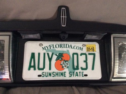
image.jpg

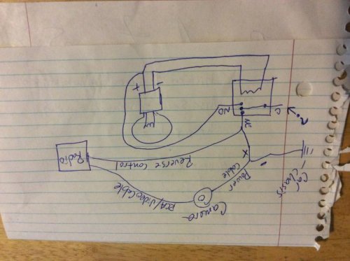
What I'm having trouble with is the wiring. I know there are other threads but only a couple I have been able to find the talk about the actual wiring and there is conflicting instruction within each. The cam came with no instructions, thanks china! Anyways, I found this diagram.....is this the way it should be wired? Additionally, which wire on the reverse light am I using, the positive or negative wire? Thanks in advance!
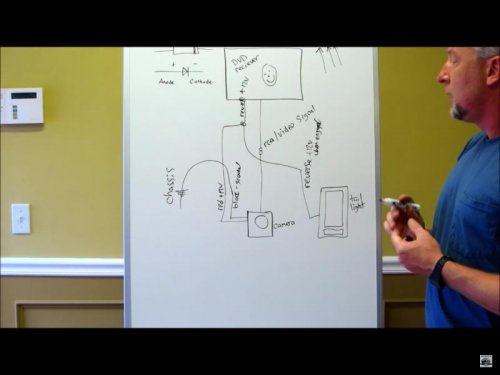
image.jpg

image.jpg


image.jpg
 
That's not going to work. The positive wire to the lights is powered the whole time the car is awake. The negative (ground) to the lights is grounded when the car is in reverse, and open otherwise. (Open makes it +12V because the low resistance bulb is connected to +12V.) You can't switch the ground to the camera because it will ground through the video cable. I had to add a relay.

Connect the coil across the two wires to the bulb. Connect one of the normally open contacts to the positive wire going to the bulb, and connect the other contact to the positive wire to the camera. Ground the negative wire of the camera. If your head-unit only accepts a positive trigger, then use the positive wire from the relay to the camera as the trigger as well.

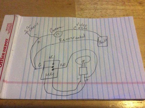
From your instructions this is what I came up with........what goes to the one labelled "?"....?

Please feel free to draw me a picture if this is not correct. :confused: :confused: :confused: :confused:
image.jpg

image.jpg
 
From your instructions this is what I came up with........what goes to the one labelled "?"....?

Please feel free to draw me a picture if this is not correct. :confused: :confused: :confused: :confused:

?
 
Yeah, that's not quite it. Maybe later I'll have a chance to draw something up for you.
 
I still haven't figured this out.
 
from what joe is saying


connect both terminals 86 and 87 both to the positive wire at the reverse bulb.

connect terminal 85 to the negative wire at the reverse bulb

the connect terminal 30 to the positive wire at the camera

ground the negative wire at the camera

make sure terminal 87a is insulated (and not connected to anything)


*normally I would have 87 and 30 reversed from above, but then you have to be careful of having 12v+ at an unused terminal any time the car is not in reverse, this way will work the same but not leave a live terminal at rest (just one less thing to short out if careless)
 
and "C" in your picture or "common" is pin 30

"NO" or "normally open" is pin 87

"NC" or "normally closed" is pin 87a

and then there are the two coil wires 85 and 86


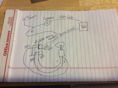
basically if you take you diagram, and move the connection from "NC" over to the "C" or "?" terminal should be it.

"NC" should have nothing attached to it
 
Or actually like this to leave no live openings to short.............

image.jpg

image.jpg
 
You might want to check the radio and see if there is a setting to have the reverse camera active on positive trigger or negative trigger. Just to verify.

If I was installing a reverse camera I would wire it as follows:

Relay:
86 - BK/GN or BK/RD (ground for back-up light bulb)
85 and 30 - OG/BK or OR/GN (power to back-up light bulb)
87 - power to camera
87a - no connection (cover terminal)

Camera ground to chassis ground

There is no access in settings for the backup camera. Thanks.
 
Have you tried to hook the camera straight to power and ground to make sure it works?
 
If nothing else works see if you can't find a momentary closed microswitch that you can install off the shift lever inside the center console. Set it so when the shift lever is locked into reverse, it trips the switch. Good luck.
 
1LoudLS...........

I wired according to this diagram as you said. But this is what I'm getting........

well that is definitely interesting...

doesn't look like the radio is liking the reverse signal its getting

first, when shifting into reverse, can you hear/feel the relay clicking/engaging? and does it stay engaged or is it also clicking on and off like the radio?


if it is staying engaged, i would either hook a meter up to the reverse wire at the radio and making sure it is getting 12v and it is steady, or i would try disconnecting that reverse wire and jumping it over to the constant wire of the radio just to see if it triggers and stays or also keeps bouncing on and off. if it doesn't stay on (since there is no way to select polarity) maybe the radio needs to see a ground signal instead of positive, try grounding the (disconnected from the rear) reverse wire right to the chassis of the radio.
 
If nothing else works see if you can't find a momentary closed microswitch that you can install off the shift lever inside the center console.

it would probably be much easier to figure out the real problem and fix that instead of rigging some other solution up
 
...since the LS is its own beast where electronics are concerned...

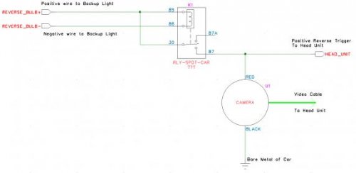
Yes, but this can be and has been made to work correctly. This is a same as some of the other schematics posted, but it it a little clearer to me.

camera.jpg

With a voltmeter connected between ground (metal of car) and the wire labeled "HEAD_UNIT" you should measure 12 to 14 volts when the car is running and in reverse, and zero (less than one anyway) when the car is running and not in reverse. What are your measurements?

camera.jpg
 
since the LS is its own beast where electronics are concerned...

no, the LS is just way different from simple cars of decades ago... its kinda just how most cars are going. once your familiar with it, and understand its differences, its not that complicated of a car. but it does confuse the hell out of a lot of guys, especially those that come from the bow tie side of things.


but more basing it on the 6 or 7 LS's that I have worked on at the shop (and the few I've done for guys from here...) and all of them working fine wired up this way, I'm still leaning toward...

it would probably be much easier to figure out the real problem and fix that instead of rigging some other solution up
 

Members online

No members online now.
Back
Top