(DIS) Charging System

dnsherrill

Dedicated LVC Member
Joined
Aug 18, 2012
Messages
2,627
Reaction score
109
Location
Raleigh
My White Car is not recharging; with the lights and a/c on it takes about 10-20 mins at idle for the bat to drain down to about 10 volts. I used a bat that I know is good and tried 2 alts:
(a)the white car's orig factory alt (120k miles), and
(b)the factory alt I took off my brown car at about 170k miles- it was functional when I removed it, iirc
---
I took them in to vato zone and tested both generators: alt(a)passed and alt (b)failed...I expected the opposite
----
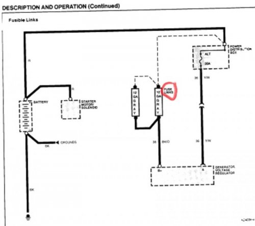
time to open the service manual: does anyone have a photo of where these 2 fuse links are located? are they just a smaller gauge wire (12ga) that becomes exposed to open the circuit?
any theories on why I'm draining/not re-charging? is it common for these to fail? maybe something elec got wet when I pressure washed awhile back:slam
----
I guess there's a ground somewhere on the block I should check? I've yet to compare the alt (+) and the bat(+) voltage.....charge at the bat does not go up if I rev the engine; I don't know how to check current from the generator
fuse links jpeg.jpg

fuse links jpeg.jpg
 
You have two small 12 gauge ish wires connected to the distribution box that feed the alt. The ground runs down to the drivers side upper left motor mount stud. Replace both and make sure you clean up the mount on the motor.
I had exactly the same problem, it was the ground in my case. I upgraded all the power wire at that time.
 
thanks JA
---
replacing those fuse links kinda seems like a pita, esp if it's unnecessary; the manual reads as though when one or both break the circuit, bare wire becomes exposed?..
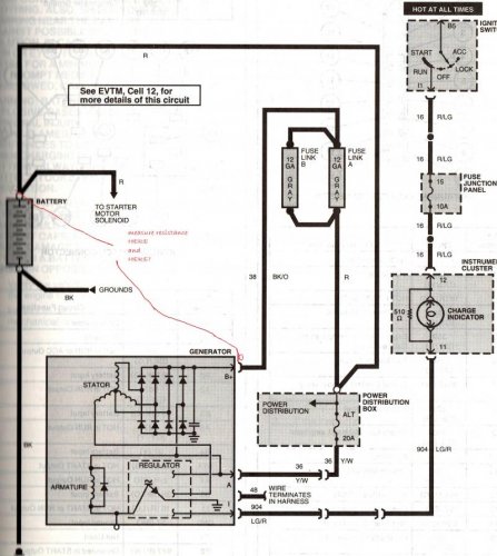
to test those fuse links, can I measure resistance between the alternator's + stud and the cable end that goes onto the + side of the bat? pass= < 0.5 ohm?
Alt scheme.jpg
---

Alt scheme.jpg
 
I upgraded the wire from the alt to the batt and to the distribution block. Both were under sized in my opinion.
Many times with aged wire it may test good from ohm load or continuity but as it draws currant the resistance will build.
I found the issue buy accident, as I watched the voltage drop on the meter I leaned over the front end to check the connections and my hand touched the negative battery cable. It was quite warm.
When I cut it open it was black half way up the cable.
If you search my post I believe I posted pictures of it.
 
If you search my post I believe I posted pictures of it.
----
found it here
----
well, my timing couldn't be worse. I parked this car last fall to do the interior swap. The charging system was not a problem then. I've since moved 60 miles away. The car is in the garage at my old house, I just go back there on the weekends and THOUGHT I was ready to bring the white car to my new residence.
Maybe my problem is a bad alt, in spite of the fact it tested good at vato zone.
I can swap it with the alt on my brown car which I know is good. Otherwise it looks like the prob/solution is rewiring. This will be new territory for me. It's only time and money, no big deal :)
---
where will I find the flexible conduit and is std black elec/vinyl tape adequate? local parts store? napa/AZ O'R, AA?
 
reference factory service manual, pinpoint tests
------
pinpointtestAp1_zps51e79a57.jpg

----
pinpointtestAp2_zpse706989b.jpg
 
... two small 12 gauge ish wires connected to the distribution box that feed the alt....
----
:confused:
the pwr dist box feeds the alt/gen (per circuit 38)? i thought the alt + post is feeding the pwr dst box?
---
where does the alt feed the batt? the red cable starting at pwr dstr box running to batt +?
----
chargingsytemschematic_zps583d3fc6.jpg
 
Follow the wire coming off the batt post on you alt, runs straight across the top.
 
10-4, that was my presumption...there's no elec charge going into the alt
 
as par for the course, I overlooked the obvious with my troubleshooting: checking the 20a fuse in position #
pwrdistbox_zps87172a51.jpg

could my failure to recharge be that simple?
 
You checked for 12 volts at the voltage regulator plug correct? If no voltage, the alternator won't excite, and obviously won't charge. Outside 2 wires should have 12 volts. Inside wire that is on earlier doesn't do anything.
 
You checked for 12 volts at the voltage regulator plug correct? If no voltage, the alternator won't excite, and obviously won't charge.
---
no, not yet, that's pinpoint tests: A8,9, and 10? (post #6)... done with key in OFF position, right?
---
I'm going back to resume the testing on Saturday; I'll take a known-good batt, and a known-good alt (from the brown car)
---
fwiw, the orig alt has tested 'PASS' at AZ twice, the second time he tested it 3x back to back to back...pass, pass, pass
 
If the alt passes over and over I'm going to say its 1 of 3 things.
Bad battery
Bad cables (ground.for sure) when the voltage starts to drop check the cables at the battery and see if they are warm. Btw.. Don't just grab them in case they are really hot.
Bad alt (regulator goes to poo after it gets hot)
 
today I did some more testing. I used the alternator and battery from my brown car which I drive everyday and know are good. both the power cable from the alternator as well as the ground cable to the engine block look good with a visual inspection. I don't see any corrosion and they both have very low resistance. Its still doing the same thing- slowly draining down While running. I have 12 volts at the voltage regulator pig tail (A circuit, Y/W wire; BUT with key to RUN i have 0 volts on the I circuit, LG/R wire and there's no voltage drop between alt B+ and batt+. the battery does not discharge when the car is not running.
----
Assuming a short is draining my system I did some troubleshooting with the power distribution box. first identified the line side and load side of each fuse holder. Then I measured the resistance between the load side of the fuse holder and ground.Fuse number 6 is a 10 amp fuse. Its for the electronic engine control and constant relay module. I checked the resistance between the load side of the fuse holder and ground. It's less than one ohm- basically an open circuit . Is this normal??? Or does it indicate a short somewhere in that circuit -all of the other fuse holders on the load side the resistance is tens of in the thousands of ohms. I recently pulled out the dash to repair the blend door so maybe I scraped some bare wire which is contacting unpainted metal? Or maybe I just have a bad PCM since that circuit is for the electronic engine control and the battery only drains when the car is running
 
I removed the fuse for the circuit in position number 6 at the pwr dst box for the EEC. the car still started and it didn't make any difference the battery still drained down so I ruled that out as my problem. Next i tested the for an open "I" circuit...the senser? What I did discover is that I may have an open circuit 904-re: schematic on post 7...a light green and red wire going from the ignition switch to the charge indicator lamp in the instrument cluster to the pig tail on the voltage regulator. When I turn the key on but don't start the engine I don't get any voltage at the pigtail for the v reg... I'm assuming that I should be getting 12 volts when the key is turned to RUN? hopefully that's the cause of my problems there's a resistor there next to the charge indicator so that if that bulb burns out you still have continuity and get a charge at the volt reg
 
I finally fixed it late last night. When I painted the dash I also painted part of the plastic connector for the instrument cluster which prevented voltage from going down the light green and red wire to the alternator voltage regulator on the I circuit. i sanded the paint off the plastic connector and that gave me 12 volts on the green and red wire when I turn the key to run. But that still didn't solve my problem! the battery still did not recharge! next i replaced the pigtail- the green and red wire looked damaged where it entered the connector. problem solved- maintainining 13.5 v!. so in hindsight my problem was all with the I circuit- it was open at the inst cluster and the there was bare wire at the pigtail into the plastic connector
 

Members online

Back
Top